EECSC106A
Hardware
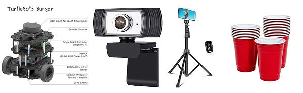
We utilized the turtlebot, cups (for the starting, goal and obstacle points), web camera and a stand.
Software Architecture
Computer Vision
Within the computer vision node, the team utilizes the command “ rosrun image_view extract_images image:=/usb_cam/image_raw” to capture an image of the obstacle course with the Logitech Camera and saves it. The “python3 image_segmentation.py” is then used to create the segmented map of the previous pictures where obstacles and map limits are identified and x-y coordinates assigned to each respective object on the map. We implement an image segmentation script which accomplishes a sequence of steps:
-
Take a picture of the environment using attached webcam
-
Crop image so only environment is shown (Figure 1)
-
Thresholding of HSV values for red and blue, using a bitwise and mask (Figure 2)
-
Erode and dilate masks using a 3x3 kernel to reduce noise and spurious pixels (Figure 3 & 4)
-
Contour detection using cv2.findContours to identify whole objects instead of instances of color (Figure 5)
-
Remove contour with largest area to remove spurious objects
-
At this point, we will have one coordinate point per colored cup. From our different masks, we also know the color of each cup. Additionally, the coordinate point should correspond to the center of each cup.(Figure 6)
-
Package the coordinate points of each cup into a single message, discerning between corners/goals (blue cups) and obstacles (red cups)
-
Publish message on the layout topic (Figure 7)

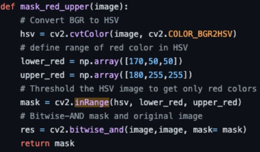
Figure 1 - capturing, resizing, and cropping image
Figure 2 - example masking function

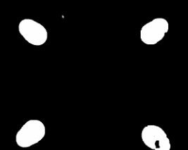
Figure 3 - erosion and dilation via kernel
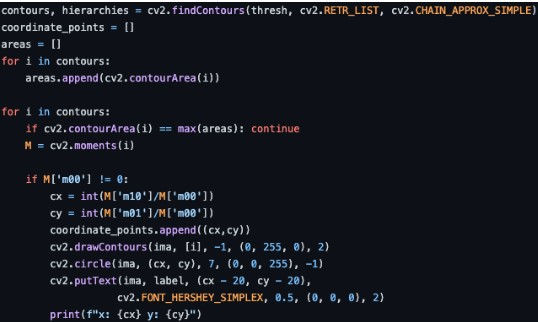
Figure 4 - resulting mask after erosion and dilation
Figure 5 - finding contours and removing contour w/ largest area
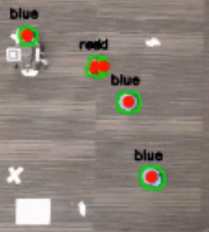
Figure 6 - example run. Every cup has a corresponding coordinate point, and color is maintained

Figure 7 - publishing image to layout topic
Path Planning
For path planning we utilized Pygame for simulation and RRT for path planning. Our workflow is the following:
-
Subscribe from layout topic, getting coordinates of all corners and obstacles
-
Create a pygame environment with dimensions equal to the area between the corners, create rectangles at the coordinates of obstacles (Figure 1)
-
Designate (0,0) as starting point, and create a circular goal at the coordinate of the goal
-
Create a graph representation of the environment, with a node at the starting position, keeping track of all parent child relationships between nodes (Figure 2)
-
Set an acceptable max step length, a larger length would mean less waypoints and a more jagged path to the goal, a smaller length would mean more waypoints and a smoother (and more optimal) path to the goal (Figure 3)
-
Randomly sample points from the environment, connecting sampled points to the closest node on the path if the connection does not collide with an obstacle (Figure 4)
-
When a point is sampled in the circular goal region and the distance between the point and the closest node is less than the acceptable max step length, send a notice that the goal has been reached (Figure 5)
-
Package the coordinate points of all waypoints along the path to the goal into a single message, and publish the message on the waypoints topic (Figure 6 & 7)

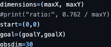
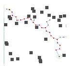
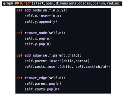
Figure 1a - creating environment in pygame Figure 1b - converting coordinates to rectangle obstacles in pygame Figure 1c - example reconstruction and full run of RRT
Fig 2. Graph object Fig 2b. parent/child relationship functions

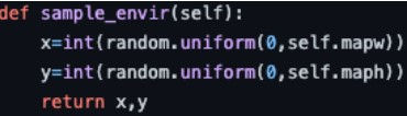
Fig 3. Step function, checks that generated point is an acceptable step length away

Fig 5. Example completed path, with a set max step length
Fig 4. Sampling point from environment

Fig 6. Traceback to find path to goal and get path coordinates
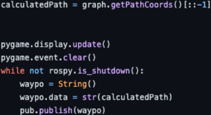
Fig 7. Publishing waypoints message
Kinematics
The intended implementation of the kinematics node is a PID controller with linear velocity and yaw control. Our attempt at implementing a PID controller was done with estimating the distance to the goal from the turtlebot by triangulation (i.e pythagorean theorem) and using that as the error function (Figure 1).
Similarly, an attempt at controlling the yaw of the turtlebot was done with an error function based on the angle formed by the triangle of the distance function above (Figure 2). With the error functions defined, we implemented an orientation search in our code which determines the direction of yaw change required (clockwise or counter clockwise ). This foundation led to the implementation of the PID below (Figure 3).
Both translation and yaw PID controllers are made up of a proportional term, an integral term and a derivative term. After implementation and during validation of the controller, the observed behavior of the PID controller was unexpected. The challenges with this implementation can be summarized in one of two categories:
-
The yaw control proved to be critically unstable. Attempts at changing the gain parameters also turned out unsuccessful. This would sometimes result in a circular motion of the turtlebot which amplified overtime.
-
Finding the right combination of the 6 parameters required for our PID controller turned out to be a little harder than expected. Our controller would often cause the turtlebot to overshoot its goal. Our approach of fine tuning was mainly empirical and there were far too many possible combinations to accomplish this in the time we had for the project.
Given these challenges, the team pivoted to a P controller for turtlebot. With this implementation, the team decided to split the control commands to the turtlebot into two separate steps. The first step consists of orienting the turtlebot towards the goal with a constant angular velocity command (Figure 4). After the orientation step is completed, the turtlebot is then moved with a constant velocity to a goal with a p controller (Figure 5).

Figure 1 - Translation error function
Figure 2 - Yaw error function
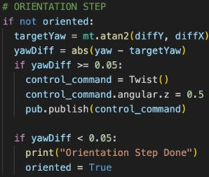

Figure 3 - PID implementation
Figure 4 - Orient turtlebot
Figure 5 - Move turtlebot